Circuit

16 x 16 readout circuit - Arduino Nano
This is a readout circuit for a 16x16 resistive sensing matrix using an Arduino Nano. We also design a connector board to quickly connect to tactile sensor electrodes. We use FFC cable to reduce the size of wires to make it compatible with robot grippers.
Schematic.
[Download]
Hardware codebase.
[Download]
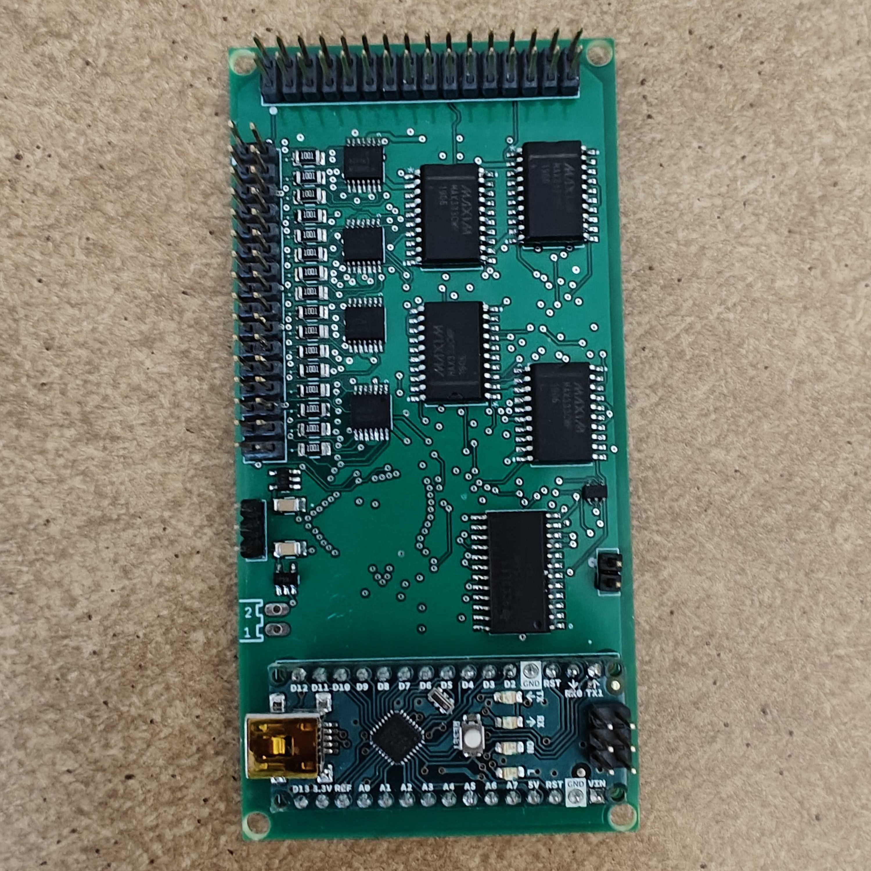
32 x 32 readout circuit - Arduino Nano
This is a readout circuit for a 32x32 resistive sensing matrix using an Arduino Nano. The architecture grounds one row at a time while maintaining other rows at a reference voltage (2.5V). A 32:1 analog switch demultiplexes the signal, reading resistances row by row. A fter measuring one row, 32 SPDT switches ground the next row while returning the previous row to the reference voltage. The Arduino controls the switches, and each sensor’s measurement is converted to a 10-bit digital signal and transmitted serially to a computer.
Schematic. [Download]
Hardware codebase. [Download]
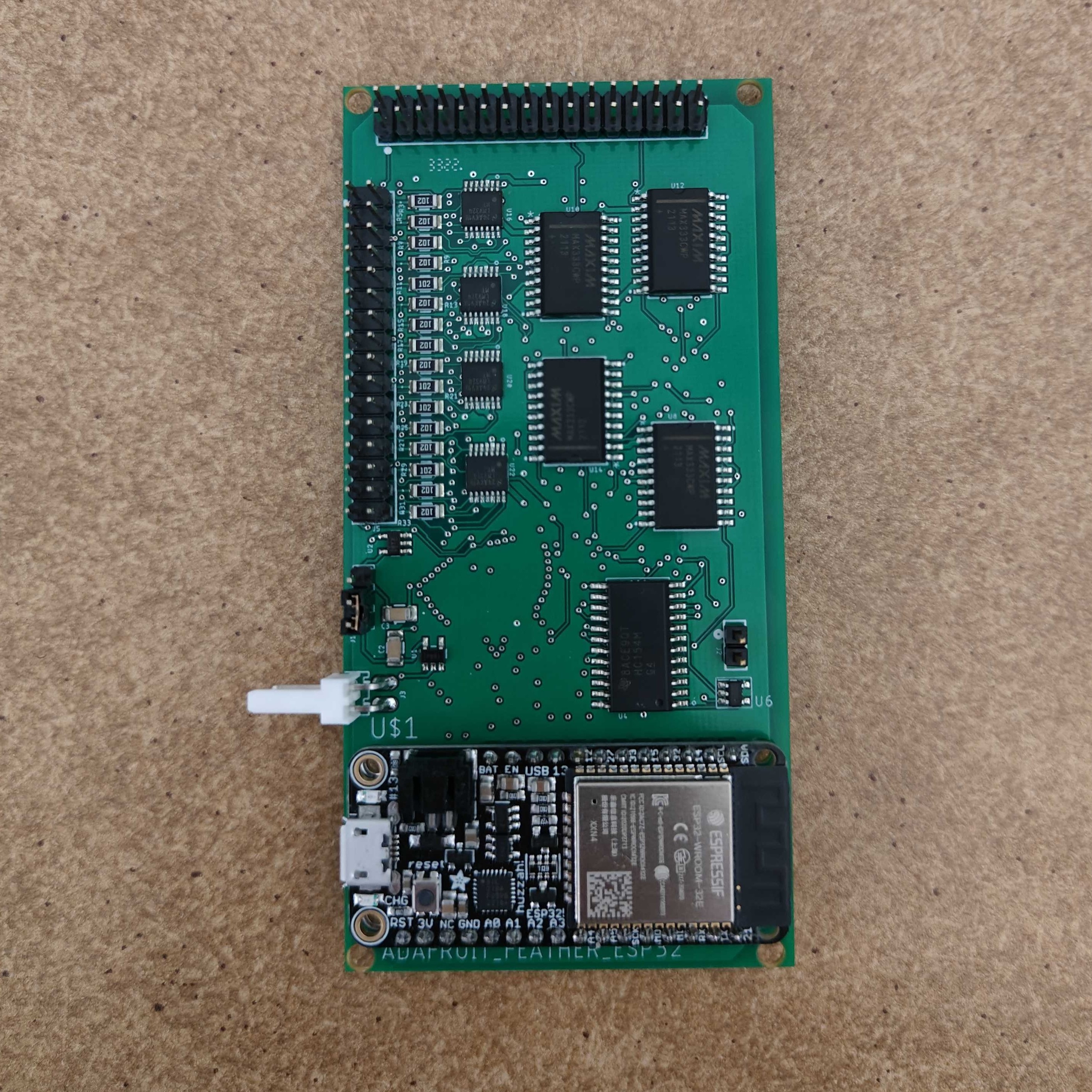
32 x 32 readout circuit - Arduino ESP32
This is an example readout circuit for a 32 by 32 resistive sensing matrix using ESP32 for wireless communication. It is a very similar architecture as the Arduino Nano version, except the rastering through the readout resistors in the matrix is controlled by an ESP32, which enables wireless communication.
Schematic. [Download]
Hardware codebase. [Download]